I wanted to make my own writeup of what was needed to substitute an ATX power supply into a G4 PowerMac, as I've been able to do it successfully to mine. Along with nice illustrated diagrams, perhaps? Absolutely. Please note that all of my diagrams are drawn from the POWER SUPPLY end, not the connector on the motherboard. This is easier for me to use as a reference to draw diagrams from as I'm coming from the perspective of modifying ATX extensions to create adapters rather than modifying the power supply itself. You can use pin numbers and the position of the latch, as well as wire colors, if applicable.
The conversion for these systems is really easy. If you look at a pinout diagram of the power connector for these motherboards, you'll notice that there are just a couple of minor differences. There's no -5v rail, instead it's another ground wire, and the place where PowerOK would be, pin 8 on a 20-pin connector, needs a 3.3v source piped into it. It's not continuous with the other 3.3v rails or this wouldn't be necessary, but it's not quite standard.
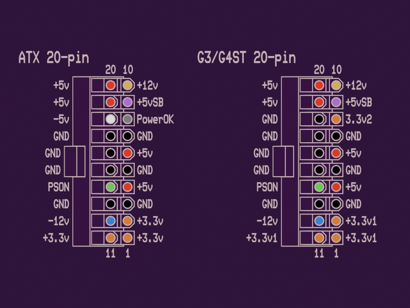
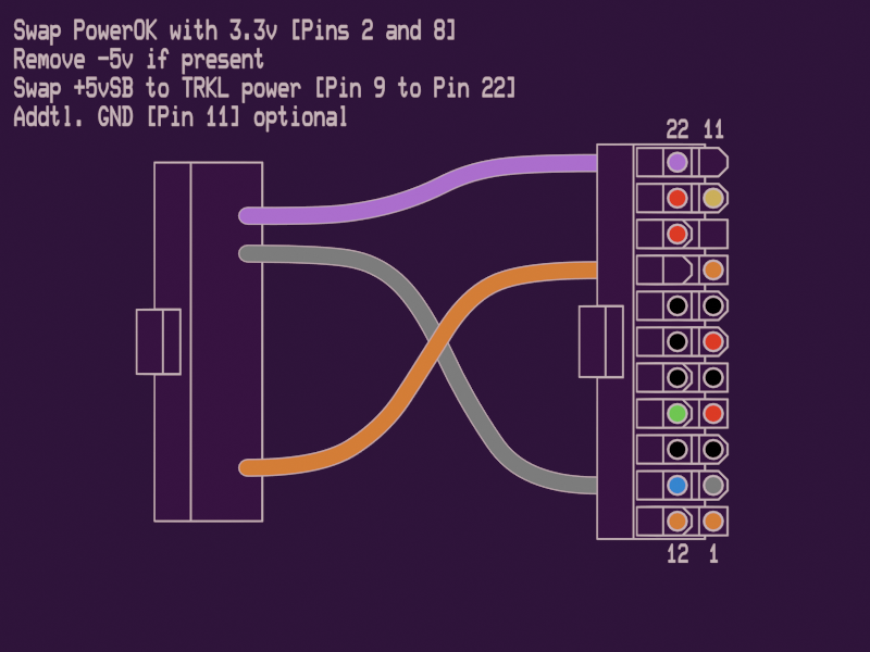
This makes adapter construction very simple. Just swap the positions of one of the +3.3v wires with the PC supplies' PowerOK signal. This allows the machine to power on and function as normal.

This is actually the one I built first out of all of them! It's almost the same as the early adapter but with a couple more differences. On these, there's a 22-pin connector for the power that has almost the same pinout as with the same differences from a PC supply as before, as well as an additional two pins for both +28v ADC monitor power and an extra ground wire. The system's trickle power has also been moved to the 28v pin, and we can do some interesting things with that.
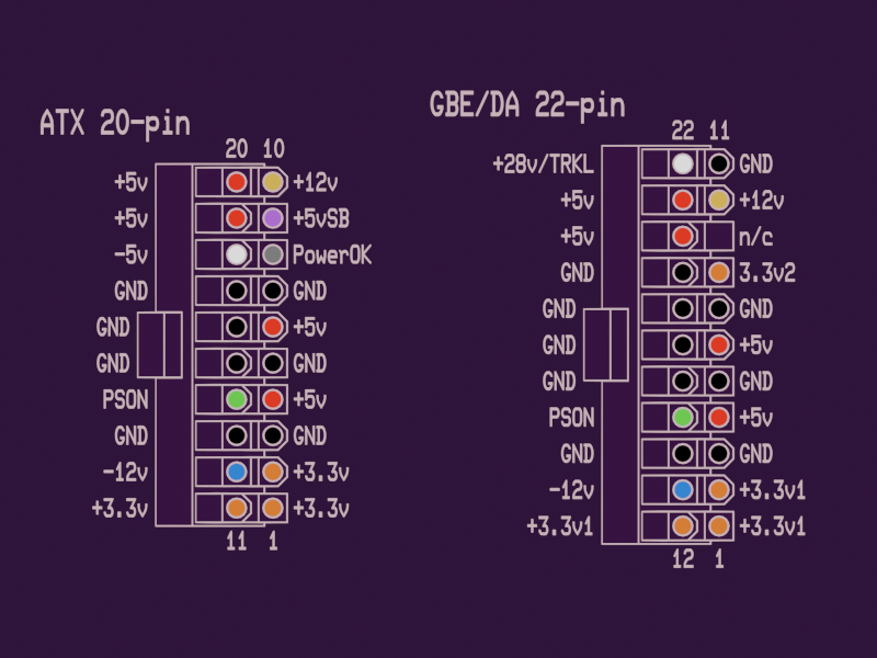
The 3.3v/PowerOK swap still needs to be done as before, for the same reasons as before. On top of that, you need to move the +5vSB power line to the +28v/TRKL power line. I tried without it, it wouldn't work. The ATXG4 guide mentioned this was necessary for the system to sleep and wake properly, and also mentions needing to use diodes to make the system feed +12v into this pin for some reason but I haven't run into a use for it. It may or may not be used for some bus powered FireWire peripherals and supplemental power for video cards, but for now I've decided to leave it off my adapter. If you start from a 20 to 24-pin adapter like I did, it might be a good idea to clip the two extra unpopulated pins with flush cutters, mine wouldn't seat until I did.
Update: I may have discovered why the 12v diodes may be needed. They mentioned FireWire being a system that needs it, and only recently did I find that my Gigabit Etherner PowerMac G4 won't go into target disk mode. It can interface with FireWire devices, but it can't act as one. That may be a reason you need to do this. I'll add another diagram with the appropriate diodes and such.

The Quicksilver's main power supply connection is ALMOST the same as a Gigabit/Digital Audio PSU except it expects +25v ADC power instead of +28v, and in two places instead of one, one of which is the vacant space left behind by the relocation of the +5vSB power rail. Like the GBE and DA PowerMac adapter, it may use the ADC power rails for certain FireWire peripherals and for extra GPU power, but for now I'm leaving it off for the sake of simplicity. I imagine the 22-pin power adapter would work the same way, but it needs a second 4-pin power connector to function as well.
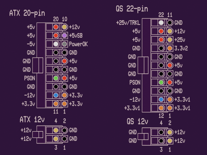
The output polarity on a Quicksilver's supplemental 4-pin 12v PSU connection is reversed, so if you swap the ground and +12v wires on a short 4-pin extension it should function just fine.

ATXG4 detailed the process of building an adapter but it is a bit different from the process with any earlier model. Instead of swapping a few pins around and being done, it's best to pull ALL of the pins out and start from scratch. The MDD uses a 24-pin power supply connector with an entirely unique pinout, but it still uses standard signals aside from that PowerOK trickery. Using all of the pins from a 20-pin ATX and 4-pin CPU connector should be plenty to get enough +3.3v, +5v, and +12v power wires to fill the adapter out.

Knowing from multiple sources, a FlexATX PSU fits well where the stock unit would have come out of, though there's not much mounting it in place, and you can also put a standard ATX or SFX power supply above the optical drive bay if you don't have any long PCI or AGP cards. The best choice would be a unit with a single +12v rail, as you'll be feeding 12v from multiple connections into the board to account for the lack of +12v power wires on a 20/24-pin ATX connector. Since the connector needs to be entirely repinned, I won't bother to draw diagrams of which pins exactly need to be swapped. It's better to build it from the ground up using both a 20 to 24-pin adapter and a 4-pin CPU connector as sources.
-Annika LaFey~, 2023-2024